 ar
ar bg
bg hr
hr cs
cs da
da nl
nl fi
fi fr
fr de
de el
el hi
hi it
it ko
ko no
no pl
pl pt
pt ro
ro ru
ru es
es sv
sv tl
tl iw
iw id
id lv
lv lt
lt sr
sr sk
sk sl
sl uk
uk vi
vi et
et hu
hu th
th tr
tr fa
fa ms
ms hy
hy ka
ka ur
ur bn
bn mn
mn ta
ta kk
kk uz
uz ku
ku
load cell wire diagram
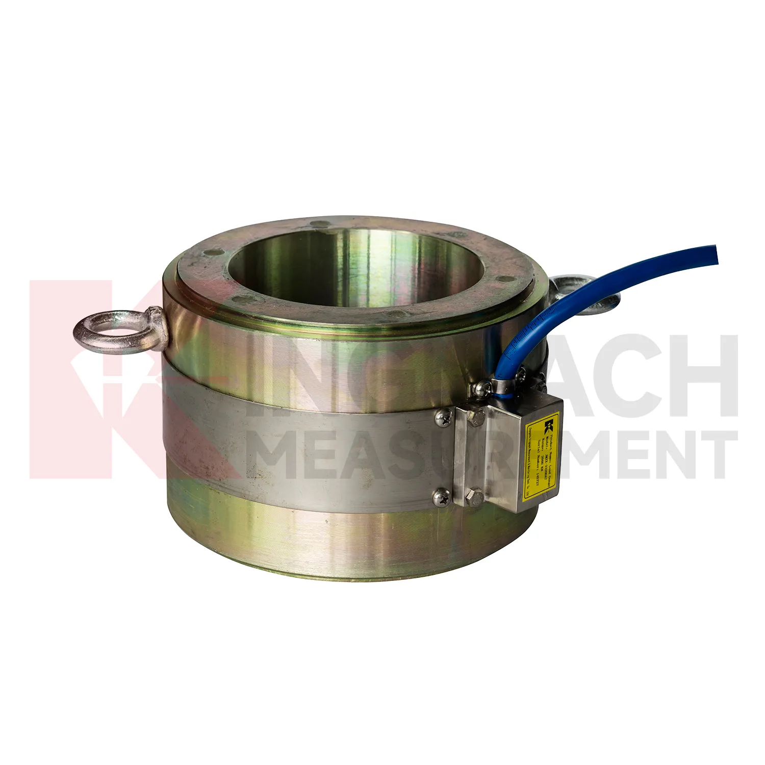
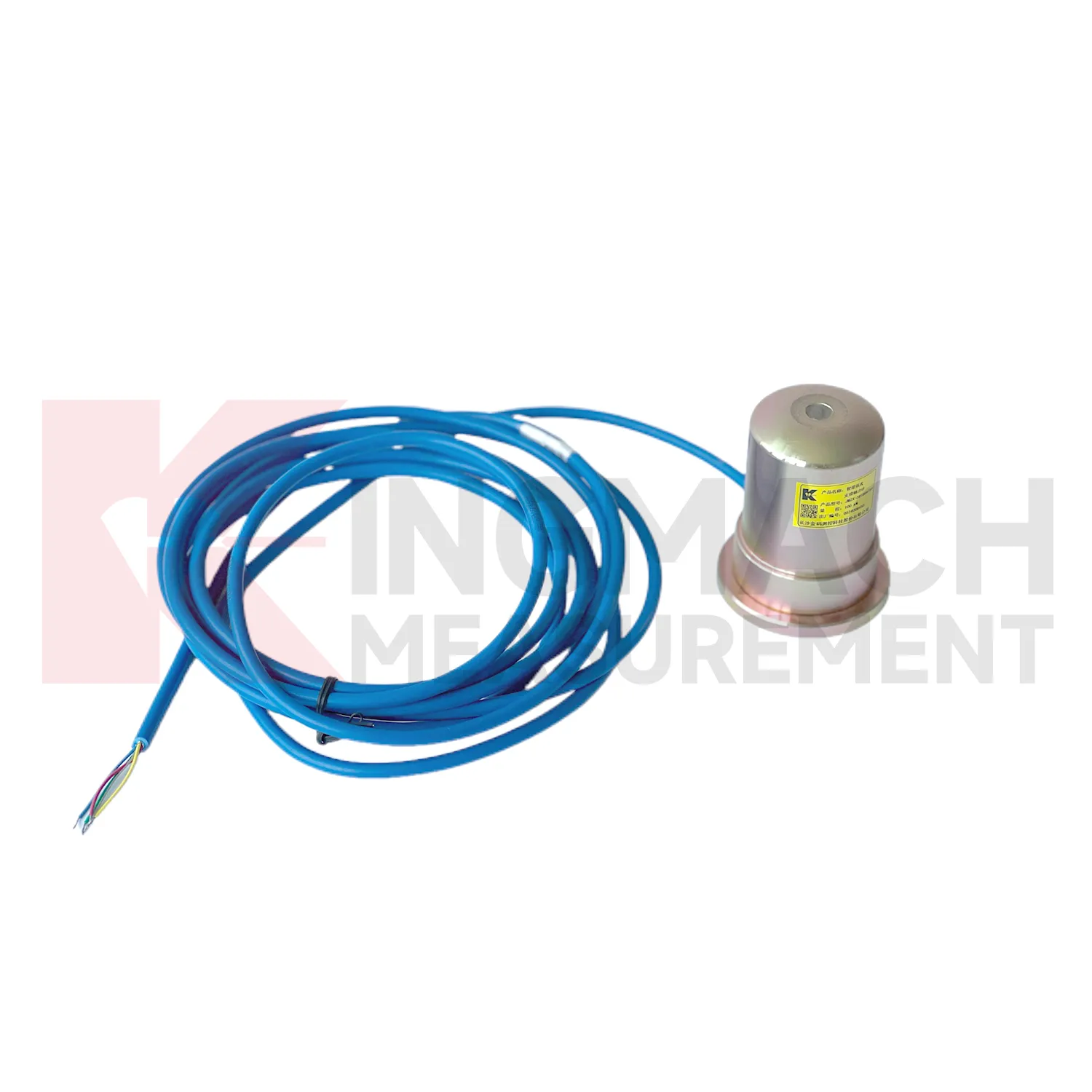
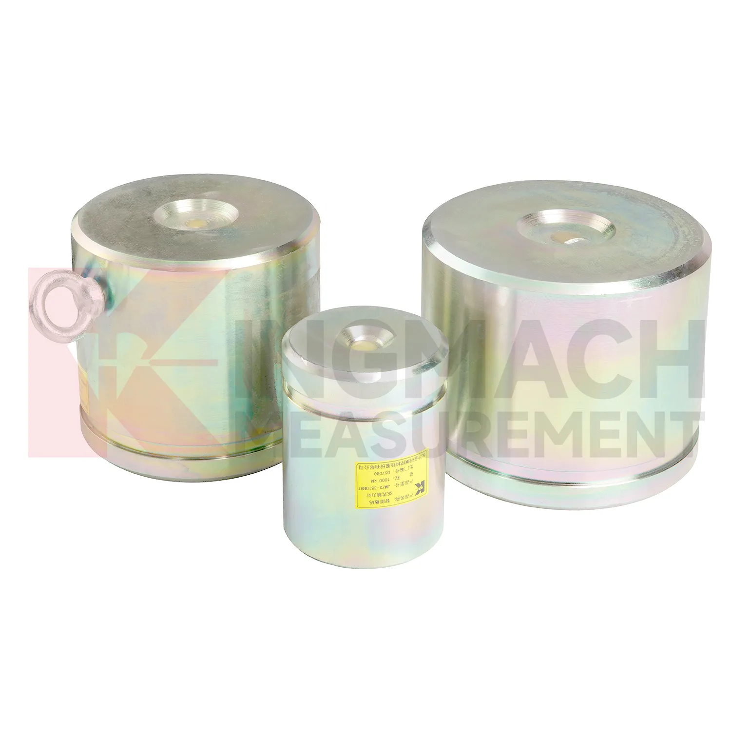
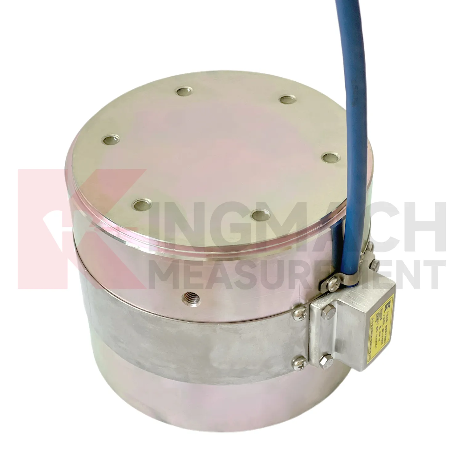
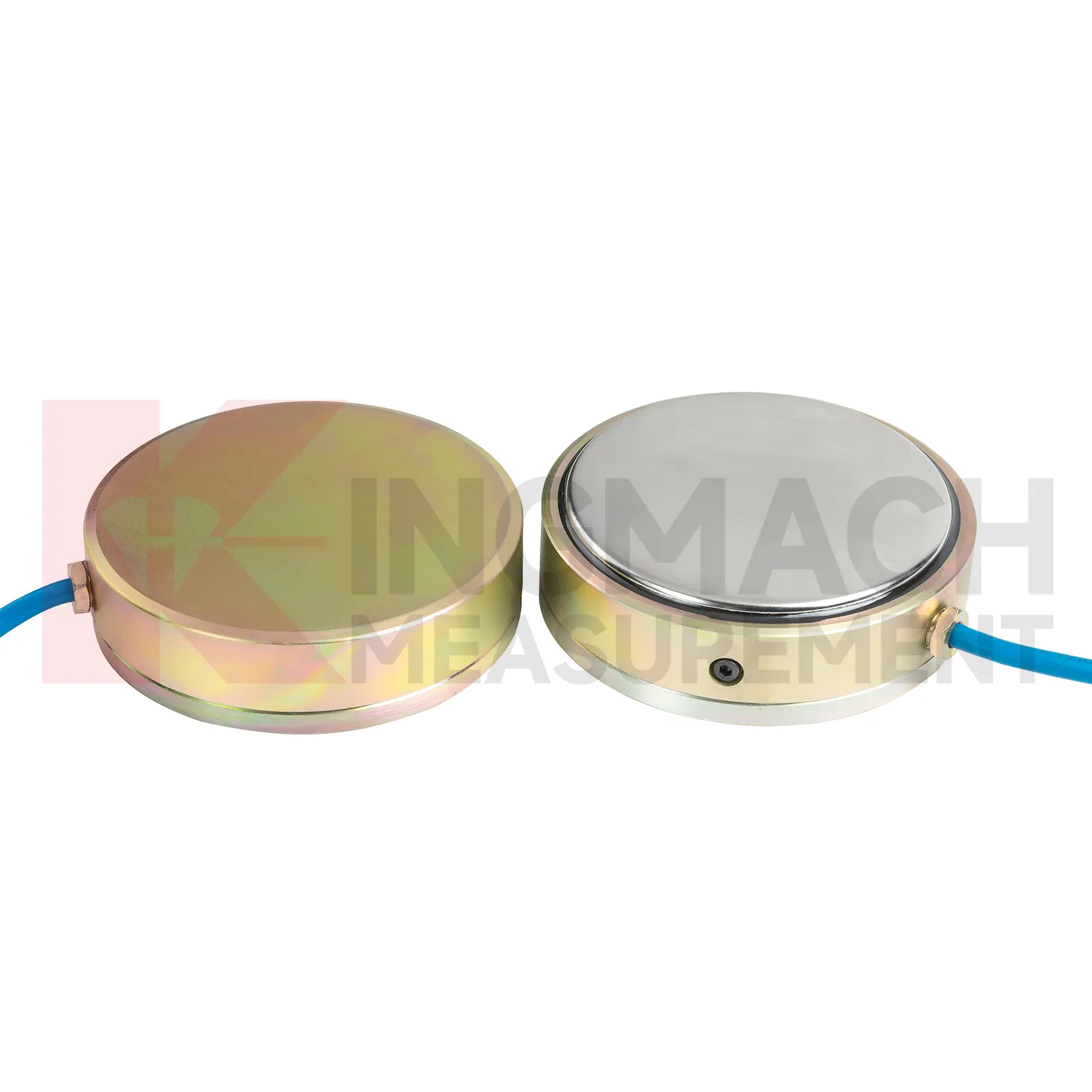
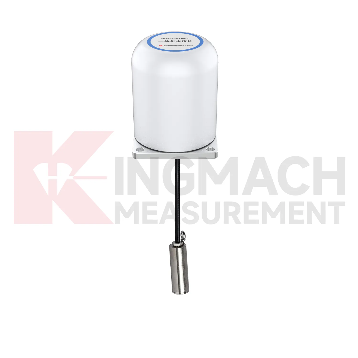
Kingmach load cell wire diagram products give engineers several ways to measure load depending on the contact condition. Hollow load cells fit cable and anchor force work, solid load cells fit compression and bearing capacity checks, axial force meters fit steel support monitoring, and earth pressure cells fit soil or contact pressure measurement. The listed technical span is broad: 500 kN to 8000 kN for hollow models, 1000 kN to 10000 kN for solid models, 200 kN to 3000 kN for axial force meters, and 0.3 MPa to 8 MPa for earth pressure cells. Accuracy and resolution are also stated in the product files, including 0.5%FS precision on main force models and 0.001 MPa resolution for pressure cells. Kingmach adds practical field features such as waterproofing, temperature correction, memory storage, digital output, and compatible readout instruments. A good specification compares these numbers with the design load, possible overload, installation surface, service environment, and planned inspection interval. This brand context fits projects that combine several monitoring categories rather than one isolated load point. A bridge or foundation pit may require force, settlement, displacement, water pressure, and software records in the same maintenance file, so compatibility should be reviewed early. The data record should also state whether the pressure or force point will be checked manually, automatically, or by both methods during handover.
Application of load cell wire diagram
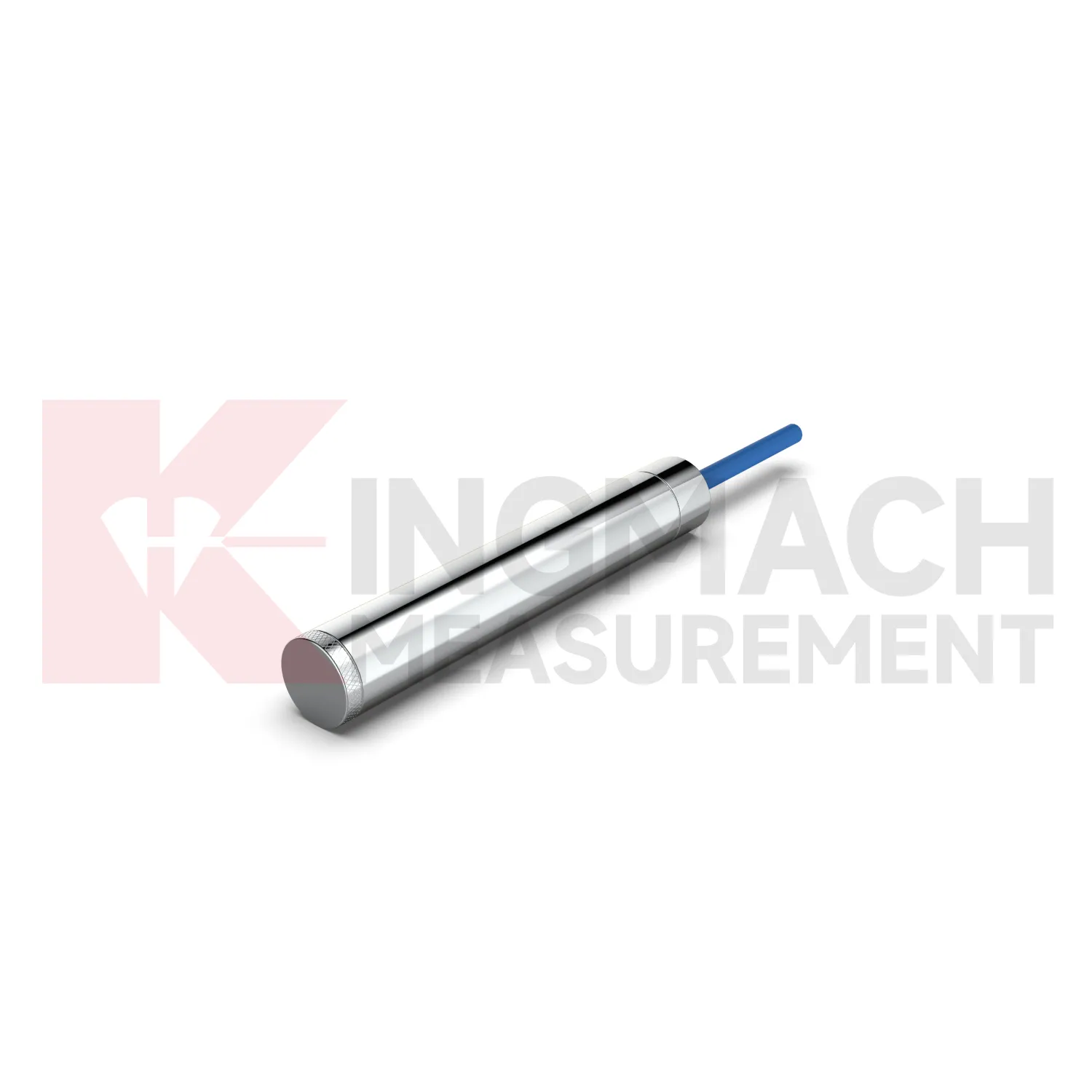
In building structural health monitoring, load cell wire diagram can be used around transfer structures, temporary supports, column load checks, foundation testing, and heavy equipment installation areas. The monitoring need is often construction stage control rather than a permanent visible defect. Loads may shift when floors are cast, jacks are released, shoring is removed, or new equipment is placed. Kingmach solid load cells offer 1000 kN to 10000 kN ranges, 0.1 kN resolution, and 0.5%FS precision, with a -30°C to 80°C working temperature range. Axial force meters add direct kN display for steel support points and 0.5%FS accuracy. These parameters help site teams check whether the support path is behaving as planned. The reading should be reviewed together with settlement, tilt, crack gauges, and construction sequence notes. For long term building owners, retaining the original model, calibration coefficient, zero value, and first stable reading makes later inspection far easier when occupancy, equipment load, or renovation changes the load pattern. In buildings, temporary works often disappear after the next construction stage, so the early record should be complete. Photographs of the installed point, bearing plates, cable path, and readout channel can prevent confusion during later structural review.
The future of load cell wire diagram
Future load cell wire diagram design will keep moving toward lower maintenance without making the device harder to verify. Waterproof structures, high strength vibrating wires, automatic temperature correction, and smart chips already reduce field workload on Kingmach models. The next steps may include better connector sealing, self-diagnosis of signal quality, power efficient acquisition, and cleaner integration with cloud platforms. For remote dams, slopes, bridges, and rail corridors, LoRa, 4G, satellite, or wired hybrid systems may be selected according to access and power conditions. Long term data also needs stable units, channel names, calibration files, and inspection notes. Without those, a smart sensor can still produce a confusing record. Future procurement may therefore ask for sensor performance and data governance together: range, accuracy, service life, waterproof rating, memory, communication method, and exportable records. Kingmach's broad monitoring catalog is well positioned for this combined hardware and data requirement. Long life hardware still needs verifiable records around it.
Care & Maintenance of load cell wire diagram
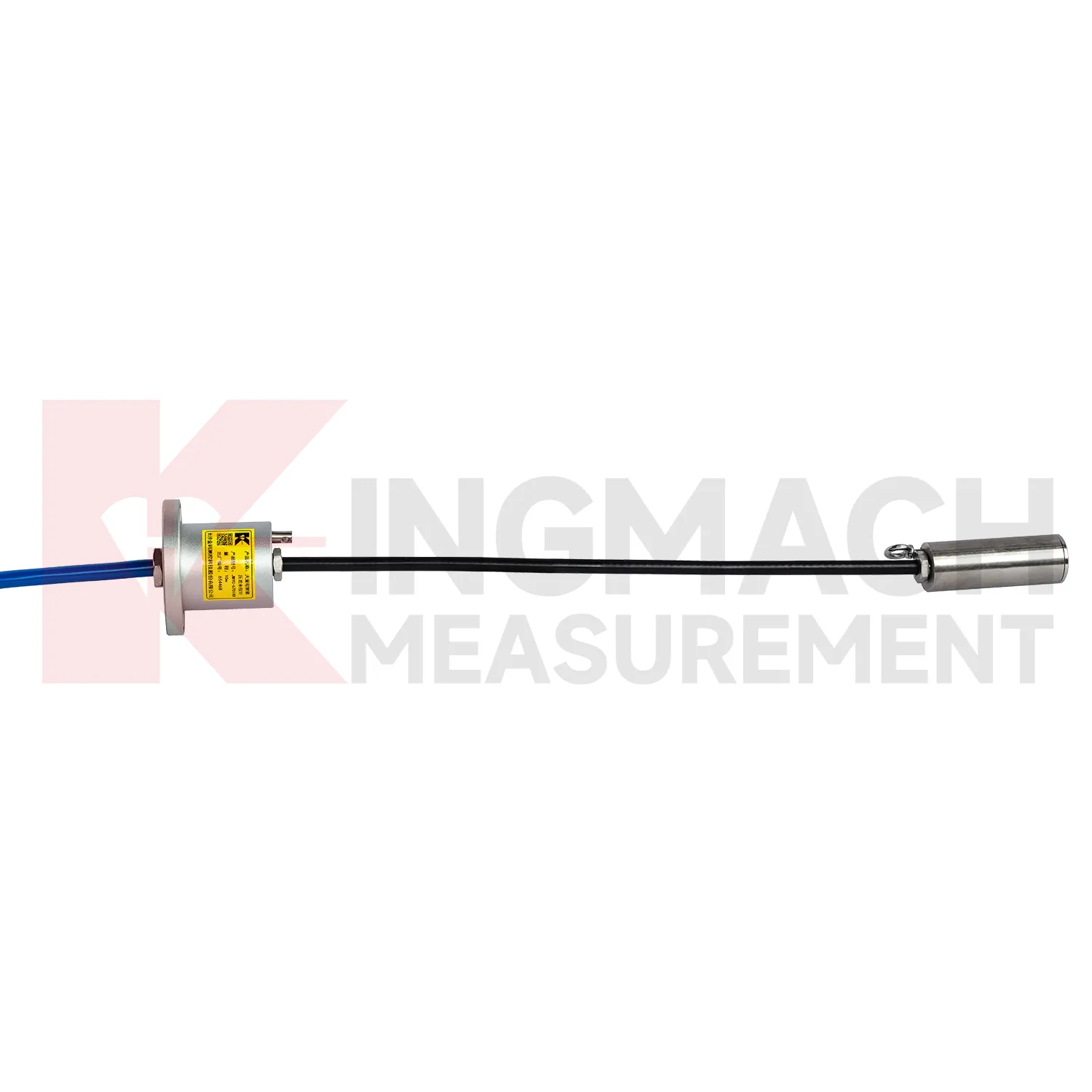
Care for load cell wire diagram should separate the installation stage from the service stage. At installation, the goal is mechanical correctness: centered loading, clean contact surfaces, adequate plate thickness, no side load, no cable strain, and a documented zero reading. The JMZX-38XXHAT axial force meter has a 1 MPa waterproof rating, but connector sealing and cable protection still need field attention. Solid load cells list -30°C to 80°C working temperature and 0.5%FS precision, so records should include temperature during important readings. During service, the goal changes to trend reliability. Check whether readings shift after construction stages, heavy rain, traffic opening, reservoir level change, or support adjustment. Keep calibration documents and channel names consistent across manual and automated systems. Where smart sensors store measurement records, download or archive data before maintenance work that might disturb wiring. Most field problems can be prevented by dry connectors, protected cables, clear labels, and routine comparison with nearby monitoring points.
Kingmach load cell wire diagram
load cell wire diagram gives engineering teams a way to follow load behavior without dismantling the structure. In bridge bearing checks, anchor testing, steel support monitoring, pile tests, and retaining wall pressure work, the measured force can change before cracks, settlement, or visible deformation become obvious. Kingmach product information points to vibrating wire and smart sensing designs, built-in memory, automatic temperature correction, waterproof construction, and direct force display on selected models. These features matter because site readings are often taken by different people across long periods. The instrument needs to preserve its identity and calibration background even when the reading method changes from manual inspection to automated collection. The most useful force record is modest but complete: point name, model, range, coefficient, temperature, cable condition, acquisition channel, and the event that preceded the reading. That is enough to make later engineering review much less speculative. It also helps inspectors decide whether a changed value needs field checking or simple trend review.
FAQ
Q: How can load cell wire diagram be connected to a monitoring platform? A: Use compatible readouts, acquisition modules, data loggers, DTUs, and software platforms according to site access, cable distance, power, and reporting requirements. Q: What makes smart models useful in large networks? A: Stored model data, calibration coefficients, zero values, temperature data, and measurement records reduce confusion across many channels. Q: Should manual readings still be kept? A: Yes, manual checks are useful after installation, maintenance, abnormal alarms, or logger changes. Q: How should alarm limits be set? A: Base them on design stage, sensor range, expected load change, temperature behavior, and nearby monitoring points. Q: What data should be reviewed together with force? A: Settlement, displacement, tilt, water level, pore pressure, rainfall, temperature, construction events, and inspection notes.
Reviews
Daniel Brown
Excellent environmental monitoring sensors. The data is consistent, and the system integrates smoothly with our existing setup.
Robert Taylor
The weir flow meter is well-built and delivers accurate measurements. Great value for water management applications.
Latest Inquiries
To protect the privacy of our buyers, only public service email domains like Gmail, Yahoo, and MSN will be displayed. Additionally, only a limited portion of the inquiry content will be shown.
Amelia***@gmail.comSingapore
Hello, I am looking for visualization software for monitoring system data analysis. Please let me kn...
Sophia***@gmail.comUnited Kingdom
Good day, we need environmental monitoring sensors including temperature, humidity, and wind sensors...