
 EN
EN
 ar
ar bg
bg hr
hr cs
cs da
da nl
nl fi
fi fr
fr de
de el
el hi
hi it
it ko
ko no
no pl
pl pt
pt ro
ro ru
ru es
es sv
sv tl
tl iw
iw id
id lv
lv lt
lt sr
sr sk
sk sl
sl uk
uk vi
vi et
et hu
hu th
th tr
tr fa
fa ms
ms hy
hy ka
ka ur
ur bn
bn mn
mn ta
ta kk
kk uz
uz ku
ku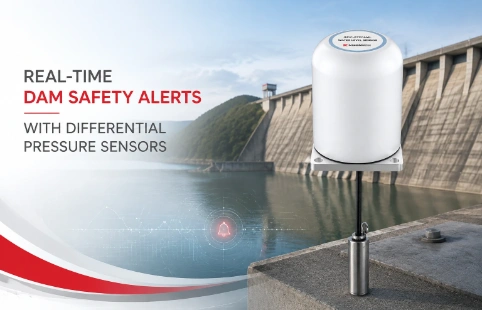
Real-Time Dam Safety Alerts with Differential Pressure Water Level Sensors
Key Takeaways An alert chain needs more than a sensor: define field in...

Load Cell Signal Conditioners That Fit Your Monitoring Setup
Signal conditioners don’t get the spotlight, but when a load cell reading drifts or a mV signal gets buried in noise, they become the most important link in the chain. Kingmach has been supplying geotechnical monitoring instruments for years, and we’ve seen how a well-matched signal conditioner can make the difference between usable data and a frustrating afternoon chasing ghost readings. Our load cell signal conditioner options are built to pair with strain gauge-based sensors — whether it’s a single load cell on a structural beam or a dozen anchor load cells spread across a tunnel lining. Instead of offering a one-size-fits-all box, we stock variants that cover common excitation voltages, analog and digital outputs, and enclosures that survive field conditions. The goal is to give you a conditioner that slots into your existing system without forcing you to redesign the wiring or power supply. This page breaks down what we offer, the technical details that matter during site installation, and how our application engineers help with the tricky parts — like long cable runs, multiple-cell summing, and matching sensor impedance.
Technical Detail
When selecting a load cell signal conditioner, practical details like excitation voltage range, output signal type, and filtering matter more than glossy brochure specs. Kingmach’s conditioners are designed around the sensors we already supply for geotechnical monitoring — think vibrating wire load cells, strain gauge anchor load cells, and soil pressure cells. That experience shapes the way we build the electronics. For example, our modules typically support a 5 to 12 V DC excitation range, which covers most foil strain gauge load cells in the field. On the output side, you can choose 4-20 mA for long-distance transmission in noisy areas, 0-10 V for local PLC integration, or RS485 with Modbus RTU for digital polling. Software selectable filtering lets you dial in response time from a few Hz to suppress wind and traffic noise, or up to 100 Hz for dynamic measurements. Another point that often gets overlooked is sensor impedance. We recommend matching the conditioner input range to your load cell’s bridge resistance — typically 350Ω, 700Ω, or 1000Ω — to keep the measurement stable. All these options come in DIN rail or IP65 field enclosures, so you can mount them in a control cabinet or next to the sensor. And because no two projects are the same, our technical team can tweak filtering, output scaling, or even add dual relay setpoints for alarms. This is not a catalog product pushed through a high-volume line; it’s a tool that gets configured for your specific monitoring setup.
News
Key Takeaways An alert chain needs more than a sensor: define field in...
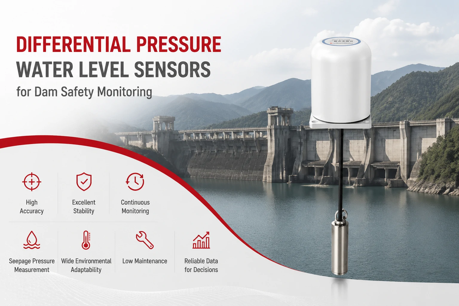
Key Takeaways The strongest fit is usually a confined, submerged, or s...
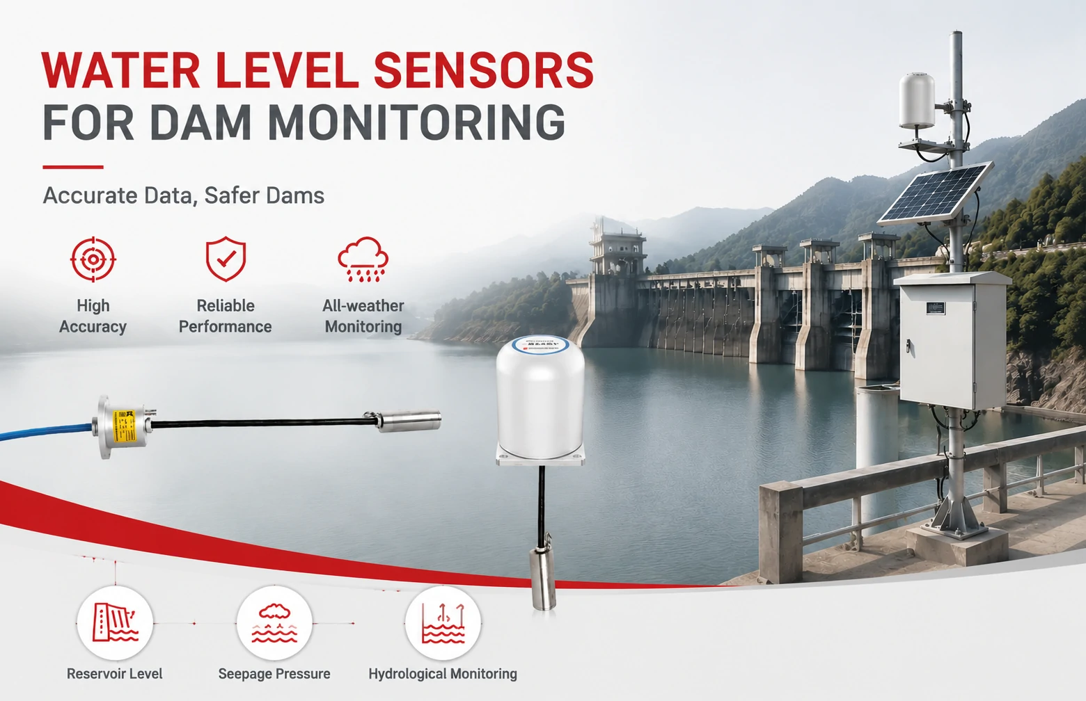
Kingmach Water Level Sensors for Dam Monitoring: A Buyer's Guide to Differential Pre...
Products
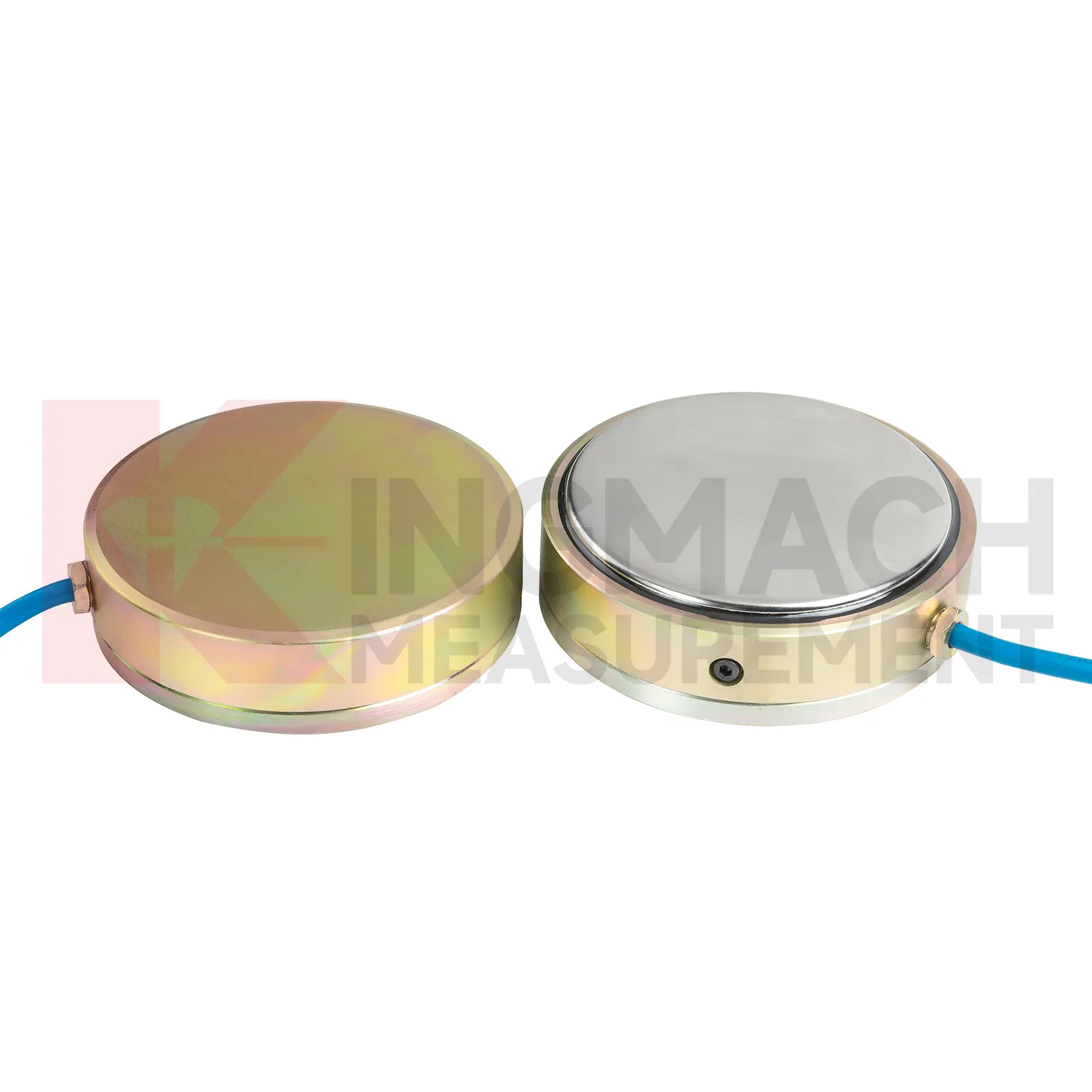
Earth Pressure Cell ( VW & Smart Type) JMZX-50XXAT/ ATM
View Details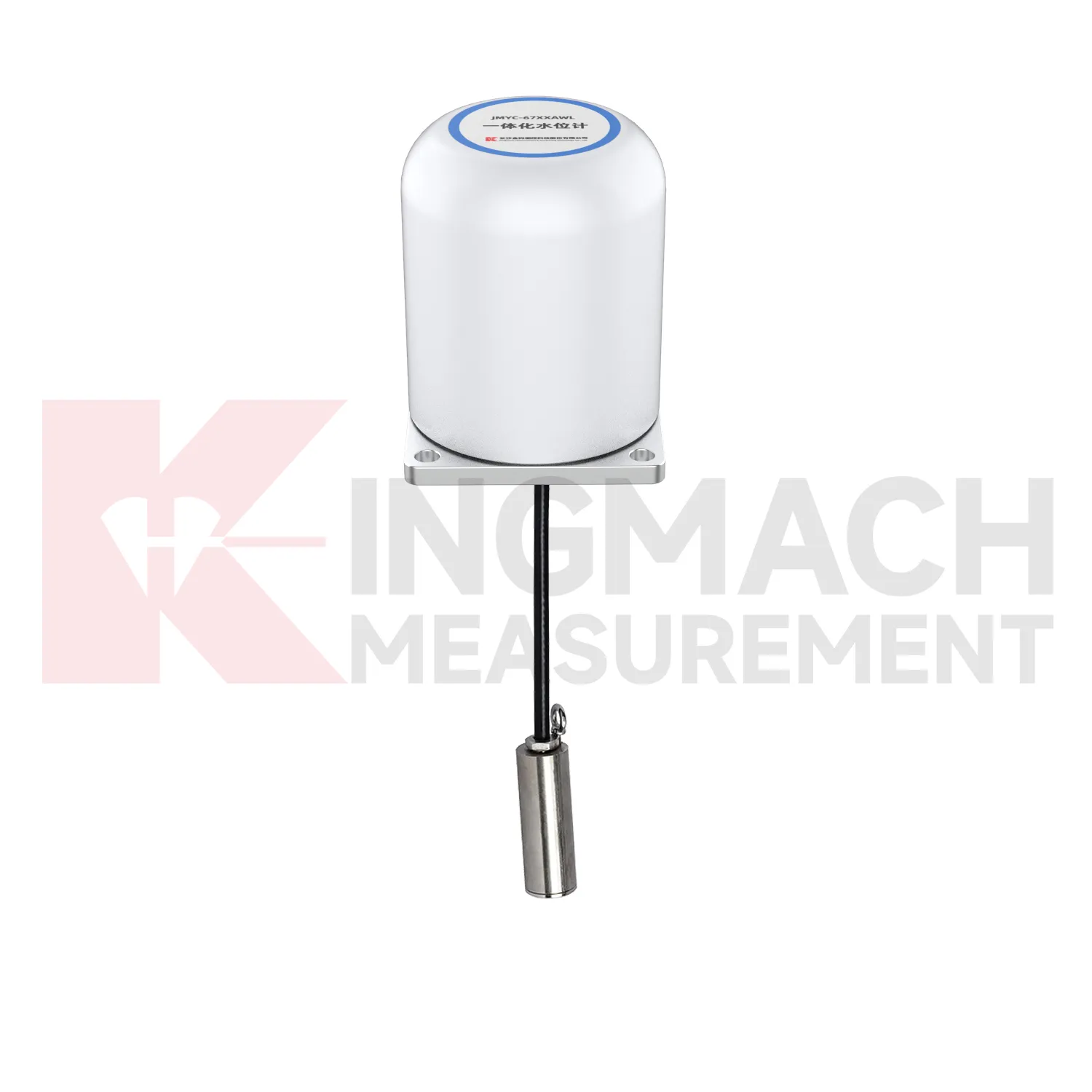
Integrated Wide-Range Differential Pressure Water Level Meter JMYC-67XXAWL
View Details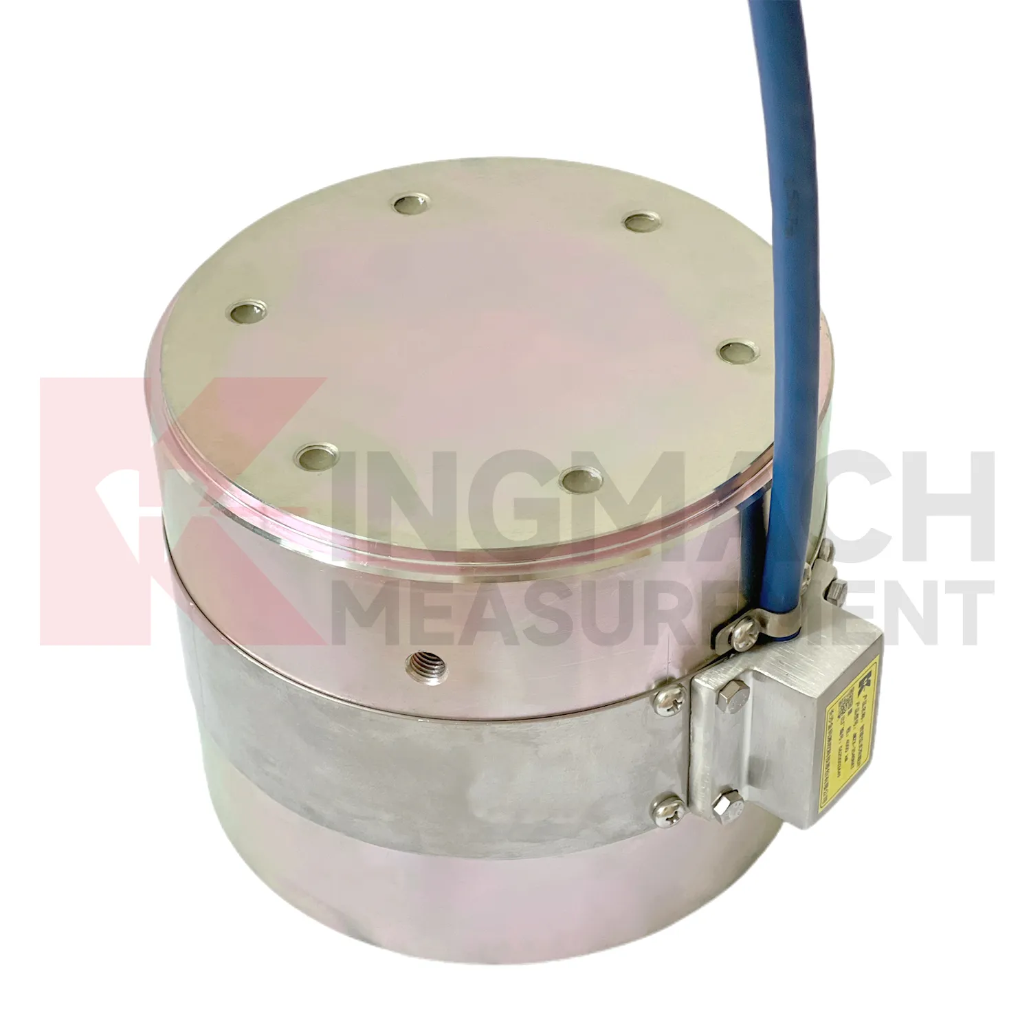
Solid load cell JMZX-34XXHAT、35XXHAT、36XXHAT
View DetailsFAQ
Start with the full-scale output voltage of your load cell — typically 2 mV/V for foil gauges. If you apply 10 V excitation, that gives a 20 mV span. Pick a conditioner that covers that span with some margin; our models accept ±10 mV to ±100 mV ranges. Also check the bridge resistance (350Ω, 700Ω, etc.) because high impedance sensors can be more susceptible to noise, and the conditioner’s input impedance should be at least 100 times higher to avoid loading errors.
Yes, but only if they are summed in a junction box first. You would wire the cells in parallel, and the conditioner sees a combined mV signal. Our tech support can help with the summing box and calibration procedure. Just keep in mind that individual cell faults become harder to detect in a summed setup.
4-20 mA current loop is the standard choice for distances over 100 meters, because it resists voltage drop and electrical interference much better than 0-10 V. For very noisy environments, RS485 digital output with Modbus RTU adds error checking and allows multi-drop wiring to a data logger.
We calibrate the conditioner to your specified range at the factory, but if you need to recalibrate in the field, our modules allow two-point calibration via a handheld programmer or software. You apply known loads (or shunting resistors) and set the zero and span points. Instructions are included, and our support team can walk you through it over a video call if needed.
Share your product type, target capacity, and application requirements. Our team can review the details and recommend a practical next step.
If you are interested in our products or want to become our partner.
Please leave your contact information, our team will contact you as soon as possible.
Mail: [email protected]
Contact Us: +8613808434127
Address: No. 188 Tongzipo West Rd, Changsha, Hunan, China